GRAPHICS ROBOT GENERATOR
ROBOTV3
|
APURVA PRAKASH
MUKUL GUPTA
Indian Institute of Technology - Kanpur : December
1997
Contents
Motivation
The whole idea Robotv3 came from the desired to develop
second generation Virtual Director. Virtual Director
is a software that converts text to graphics using some predefined dictionary.
It has modules for text parsing, object identification, spacial reasoning,
motion planning, etc. Virtual Director has very poor graphics developed
using Starbase. Moreover, it has predefined functions for every object
in it's dictionary, which preverts further generalization of it's domain.
Hence came the need for a more generalised structure for it's graphics
module.
Introduction
Robotv3 is an articulated object editor and simulator
used for animating robots and other articulated objects in 3D with action
dynamics.
How it works
Any 3D scene to be modelled can be represented in the form
of a tree, where the base node is the world frame or the frame of reference.
Branches of the tree are objects or robots either static or dynamics in
the world frame, which in itself are further branched out.
The object structure can be divided into two parts
Skeleton frame of local coordinate systems on each joint,
with the type of the joint.
Body geometry of the object in that skeleton frame.
Using a push and pop stack system for the transformation
matrix, the whole tree can be traversed, thus creating the desired scene
or the desired object in the scene.
How to define
the Input
The input consists of three things :
Skeleton frame defined using four parameters - a, alpha,
d, theta. This convention can be read in more detail in the third chapter
of the book "Introduction to Robotics, Mechanics
and Control" by
John J. Craig. Parent link no. or frame
no. is also defined for each frame or link. Joint type and range is defined
as revolute or prismatic by the value of d or theta.
Body geometry is then defined in the skeleton frame locally
in each coordinate system using some predefined 3D primitives like cylinder,
sphere, cuboid etc. Body geometry is then positioned and orientated in
the local frame using five parameters - x, y, z, theta, phi.
Motion is defined using a seperate set of data, which has
frame or link numbers with the new value of the joint parameter d (prismatic)
or theta (revolute), defined at each time step.
The whole input is a set of numbers which can be manually
entered into a file and can be read into the program robotv3. Motion data
is to be specified into a seperate file and can be read afterwards.
Sample Input File for Skeleton and Body Geometry
:
26
# Total no of frames
22
# frame 1, parent link = 22
-90 0 0 0
# alpha(i-1), a(i-1), d(i), theta(i)
0
# Joint type Revolute
-50 0 5
# Joints lower, upper limit and step size
1
# 3D primitive type - Cylinder
0.1 0.3
# Radius and Height of the Cylinder
0 90 0.1 0 0.34
# theta, phi, x, y, z
...
...
Sample motion file
3
# No. of links whose value you are changing
2 0.000000
# Link no. and it's new value
25 0.000000 # Total
8 links are changed
27 0.000000
4
# New time frame, again 8 links are changed
19 0.000000
20 0.000000
23 59.999996
24 -119.999992
...
...
Results
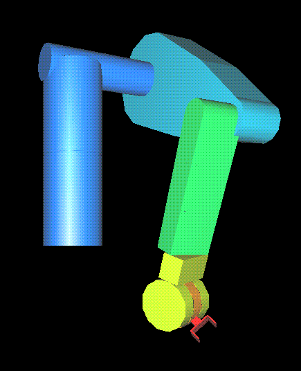
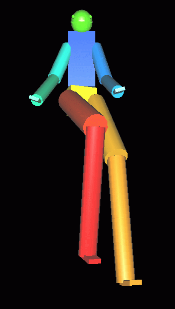
Some models have been simulated by us using this program
like a hand, a man and a robot called PUMA. See
them here on this page.


Puma Robot
Man Model
The model of the man was used in another course project called
"From
Footprint to Animation" also. Look
this page for it.
Program and
available Features
The code is written in C language and uses OpenGL libraries
for graphics.
Some features available in the program are :
Wire Frame or Solid Frame Model.
Lighting On/Off.
View Angle Adjustments.
Zoom In/Out.
Orthographic or Perspective View.
Motion On/Off.
Soon executables of this program will be available
here on this page.
To ask for a copy of the program contact me at [email protected]
Scope for Improvements
At present, the input data has to be entered into the program
manually. There is no user interface available for it, which makes this
activity a little boring and difficult to edit. A user interface can be
expected in near future.
References
"The Virtual Director", by Singh M. P., Mishra N. K.,
Mukherjee Amitabha in "Conference of the Computer Society of India"
"Introduction to Robotics, Mechanics and Control", by
John J.Craig, Addison Wesley Publishing Company, Edition May 1988, Chapter
3, "Manipulator Kinematics".
"From Footprint to Animation", by Michiel van de Panne,
Journal "Computer Graphics Forum", year 1997, volume 16, number 4, pages
211-223.
This project was made by Mukul Gupta and Apurva
Prakash in December Semester, 1997. (Guide : Amitabha
Mukerjee )
This page was last updated on 21st July, 1998.