Last Year's BTP - Omnidirectional Robot
|
|
APURVA PRAKASH
RAHUL PANDEY
RISHI KOHLI
Guide : Dr. Amitabha Mukherjee
Indian Institute of Technology - Kanpur
Apart from the general application of the omnidirectional robot as described above, our omnidirectional robot is being made with the ultimate aim of it playing in the soccer-playing robot competition. In the past few years, a lot of robots have been made in the institute with the purpose of being used in this competition. Without omnidirectionality, a quick and smooth motion in all directions was not achieved and hence the performance of the robots was not very good. For playing soccer, the robot should have all the three degrees of freedom (x, y, w) and should be able to change its position and orientation very quickly. This can only be achieved with omnidirectionality.
Moreover the soccer playing robots made in the past were
large in size. Our objective is to make an omnidirectional robot, as small
as possible.

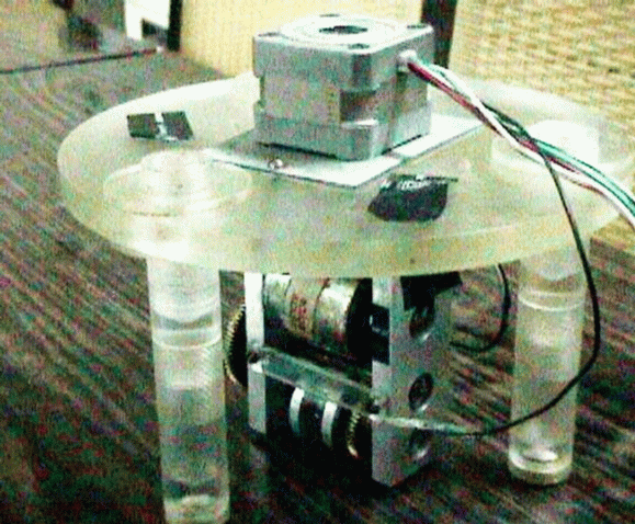
Last Year's BTP - Omnidirectional Robot
Last year also, a group had made an omnidirectional robot
but that was a pseudo omnidirectional robot. It had two motors, thus allowing
two degrees of freedom - x and w. Thus the robot had to be rotated in order
to translate it in a new direction. Moreover, it used the principle of
sprung and unsprung mass. The mass, which rotated, was very small so that
moment of inertia was not a problem but the bigger mass also rotated with
the smaller mass, due to absence of needle pivots in the legs of the robot.
Hence, controllability became a big problem in the robot, as there was
no feedback mechanism to determine the position and orientation of the
robot. Thus, this robot was not truly omnidirectional.
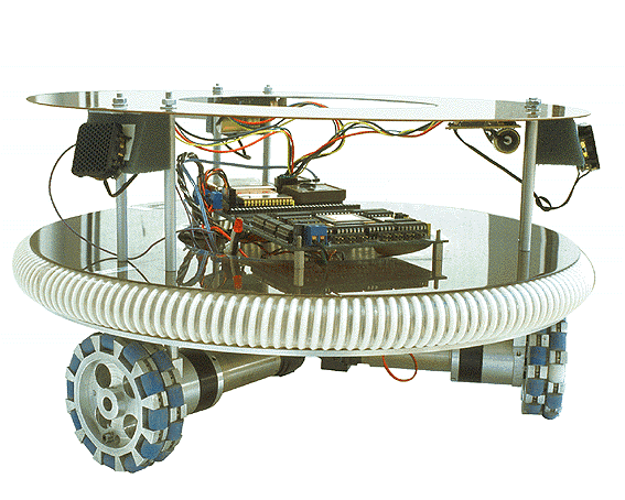
Omnidirectional Robot made using Universal Wheel Concept
* Orthogonal Wheel Concept - A round platform with
three sets of wheels underneath, where each set of wheels consists of two
wheels which look like miniature balloon tires. The wheels in each set
are mounted in a cage at right angles to each other. There is one motor
for every set of wheels and the motor rotates the cage in such a manner
that at any time, one of the two wheels of every set is in contact with
the ground.
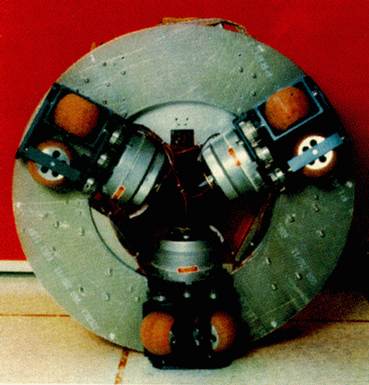
Proposed Model - Orthogonal Wheel Concept
In the first design, as the drive shaft turns, the wheel
is driven in a normal fashion in a direction perpendicular to the axis
of the drive shaft, i.e., in the constrained direction of motion. At the
same time, the small rollers allow the wheel to freely move parallel to
the drive shaft, providing the unconstrained direction of motion. Wheels
of this type must be relatively large to accommodate the rollers and greatly
suffer from the successive shocks caused when individual rollers make contact
with the ground. Hence this design is not very good and is ruled out. The
second design provides full omni-directionality with independently controlled
rotational and translational degrees of freedom. It does not have any glaring
errors and its concept is discussed in detail below.
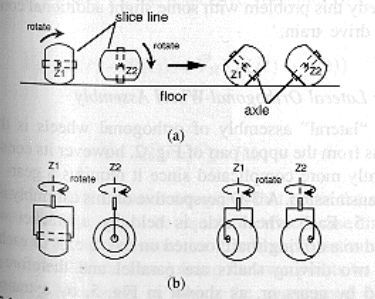
Orthogonal Wheels : (a) Side View, (b) Top View
Each wheel can be driven to roll on its portion of spherical
surface, rotating around an axis - Z, perpendicular to the wheel axle.
When these axes (the axes of the two wheels of a set) are maintained parallel
and at a constant distance from each other, and when the wheel rotations
around these axes are synchronized, contact with the ground can be assured
by at least one wheel. In principle, the proper orientation of the system
has no requirement other than the parallelism of the Z rotational axes
of the wheels, constant spacing with the ground of the sphere's center,
and the synchronized successive contact of the wheels with the ground.
When the wheels are rotating in synchronized fashion, they are driven in
the direction perpendicular to the Z axes. In the meantime, whatever wheel
is in contact with the ground can roll freely in the direction parallel
to Z, therefore allowing the entire wheel assembly to move freely in that
direction.
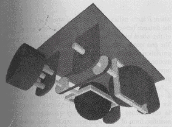
Laternal Orthogonal Wheel Assembly
Orthogonal Wheel assembly has a constrained and controllable
motion in the direction perpendicular to the shafts while it is freewheeling
in the direction parallel to the shafts. Full three-DOF omni-directionality
can be achieved with proper control of the constrained and unconstrained
directions of motion. Also, rotation of the assembly around any vertical
axis takes place with no slippage of the wheels and without discontinuity
in the motor speed.
Thus the rigid body constraint requires that either the
velocity vectors of the two points be equal or the projections of the velocity
vectors on the line joining the two points be equal. For this assembly,
this constraint implies that during any motion of the assembly, both wheels
are required to turn at the same speed in their constrained direction.
Therefore, no discontinuous change in the motor speed is necessary when
ground contact switches from one wheel to the other. Moreover, both wheels
could be in contact with the ground and no slippage would occur since the
motor drives both the wheels at the same speed in the constrained direction.
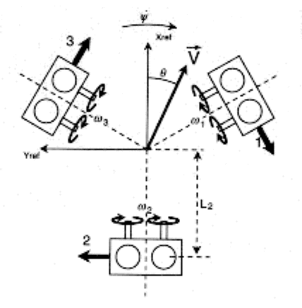
The advantageous feature of this model is that the values
of L are the same whichever wheel of a set of two wheels is in contact
with the ground so that the velocity of both the wheels relative to the
center of the robot's body remains the same. The wheels' driving shaft
velocities are calculated in terms of the platform's rotational and translational
velocity as given below :
Hence in Matrix form
Where,
The first two terms in the rotational velocity of the
wheels represent the projections of translational velocity |V| on the constrained
motion directions of each assembly, while the last term represents the
components due to the rotational velocities of the platform. As can be
seen from the equations, the rotational and translational motions are fully
decoupled and can be controlled independently and simultaneously. The platform
can fully access the three degrees of freedom of planar rigid body motions
with no constraints or compatibility conditions on the three independent
controls.
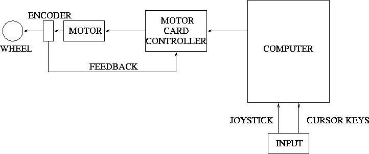
In teleoperated mode, the signals from the joystick directly
provide the values of the translational and rotational velocities.
When the user provides the trajectory, the target configuration is compared
at every loop cycle to the current estimate of position and orientation.
The results provide the desired direction of motion and the platform targets
rotational and translational speeds using linear ramp-up profiles , up
to the preset maximum velocities. The corresponding shaft velocities are
calculated and are used to check that the maximum allowed shaft velocity
is not exceeded. If this is the case, all velocities are decreased by the
ratio of the calculated to maximum velocity prior to being fed to the servo
controls. When the platform comes within a certain radius or within a certain
angle from its target orientation, the calculated translational, or rotational
velocity, is decreased using linear ramp-down profiles. When the location
and rotation angle are both within given thresholds from their target values,
a new entry is read from the list and becomes the target configuration,
or the platform stops if the list is exhausted. At each loop cycle of length
'dt', the system integrates the rotational and translational velocities
to estimate the current orientation and position of the platform.